Building a real, self-driving car!
You’ve probably seen me write quite a few articles on the components of the self-driving process (which were quite technical!). For the past few weeks, I’ve been working on building my own, real self-driving car that can drive real-time.

Let’s break this stuff down, so simple that even you’ll be able to understand.
The TLDR; of how I built this
I used ROS (Robotic Operating System), to help successfully communicate between the traffic light detection nodes, a waypoint updater node, and a drive-by-wire (DBW) node via the use of data from sensor fusion (don’t know what that is, click here). The self-driving car works by using a waypoint updater algorithm by creating a trajectory (set of waypoints), the car can follow the path correctly while ensuring passenger safety.
System architecture
Here’s a rough outline of how the self-driving outline worked and the ROS nodes + topics that were used.
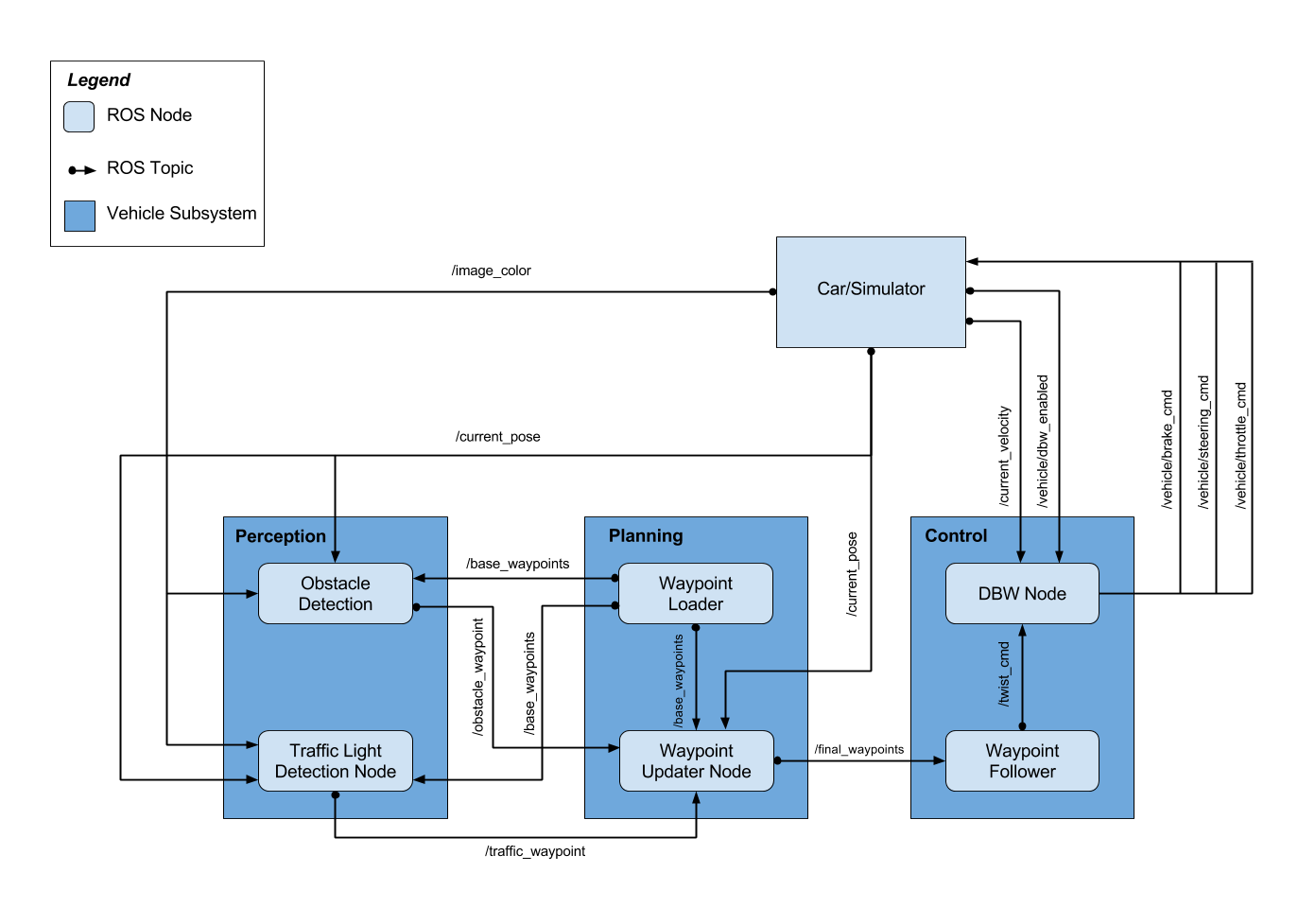
A ROS node is essentially an operator, given certain data, it performs certain operations (think of it as a calculator, in this case, it would be executable code that we’d write) and then uses that operation to publish it to a topic.
Generally, when we work with ROS, we can subscribe and publish messages to a certain “topic” (like a category, ex. the topic of a soccer node would be sports). In this case, the ROS topic allows us to provide information (and update) information (which would be the outputs of a ROS node) to the ROS nodes which are “subscribed” to the topic.
For example, if you look at the Traffic Light Detection node, you’ll notice that it’s subscribed to 3 topics: traffic_waypoint, current_pose, and image_color. That data is then shared among all the other nodes in the ROS system → for the traffic_waypoint topic, the 2 nodes subscribed are the Traffic Light Detection node and the Waypoint Updater node.
All this data is pulled from the Car (simulator).
Traffic Detection
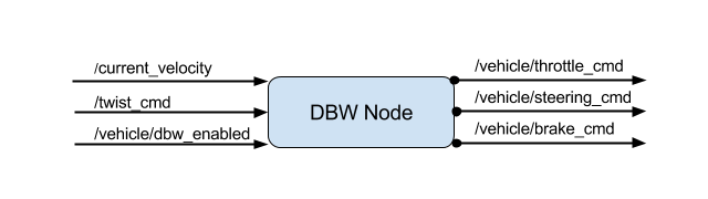
Getting a close-up perspective on the Traffic Detection node, this is how it looks like.

We’re taking in data from our current position, the base waypoints (the trajectory the car will be following), and the image colour (in the sense of the colour of the traffic light → we had the option to use a Deep Learning pipeline for traffic light detection so we’d have to take in the image colour). We would then publish (output) the locations where the car needs to stop for traffic lights.
Waypoint Updater
The purpose of the waypoint updater node is to basically allow us to update our target velocities for each waypoint given the traffic light + obstacle detection data (camera + sensor fusion input respectively). We would then publish a new list of waypoints ahead of the car with the desired velocities while incorporating the velocities of the car.

DBW
Drive-by-wire (DBW) is a type of system that CARLA (Udacity’s self-driving car) uses. What this means is that the throttle, brake, and steering values all have an electronic control (no mechanical control, we’d use this electronic system to activate these functions).
We would use our inputs from the current velocity to help generate target linear + angular velocities. We would then publish throttle, brake, and steering commands.
Breaking all of this down
As you might’ve noticed, there are 3 main steps with respect to the Perception, Planning, and Control steps; the traffic light detection, the waypoint updater, and the DBW steps. Let’s break this down and how all of this really works and plays a part in the overall building of the self-driving car.
Perception
In the 2 nodes as seen in the System architecture diagram, we have both the Object Detection and the Traffic Light Detection node.
Let’s start with Object Detection. This does include Sensor Fusion and the use of LiDAR and Radar sensors to help figure out as to where we can drive and where we can’t.
Additionally, we can also use camera-input to detect object detection for cars and objects that sensor fusion might not even be able to detect. Although I did not opt in to chose camera-input because the Sensor Fusion algorithm worked fine, here’s how the camera rundown would look like.
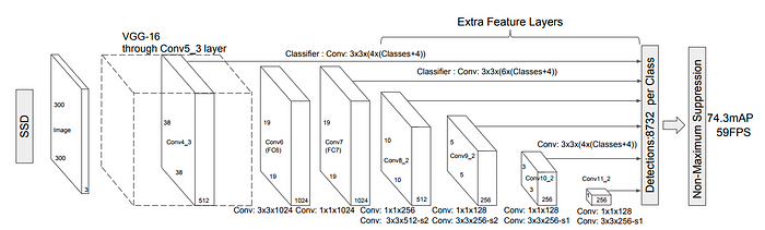
We’d use a special type of Convolutional Neural Network (read more here) known as a MobileNet-SSD. It mainly follows 3 steps:
- Perform depthwise convolutions with 1x1 convolutions (this is also known as a pointwise convolution) vs. a vanilla convolution.
- From there, use a “width multiplier” which allows the size of input + output channels to be thresholded between 0 and 1.
- We’d also then use a “resolution multiplier” to reduce the original input size and threshold to 0 and 1.
Remember to note that MibileNets and designed specifically for usage on mobile devices, not cloud GPUs. Even though more parameters would allow for a more accurate model, remember that we want to run this real-time, in dynamic environments where the FPS (frames per second) matter.
Here’s what the overall CNN architecture would look like:
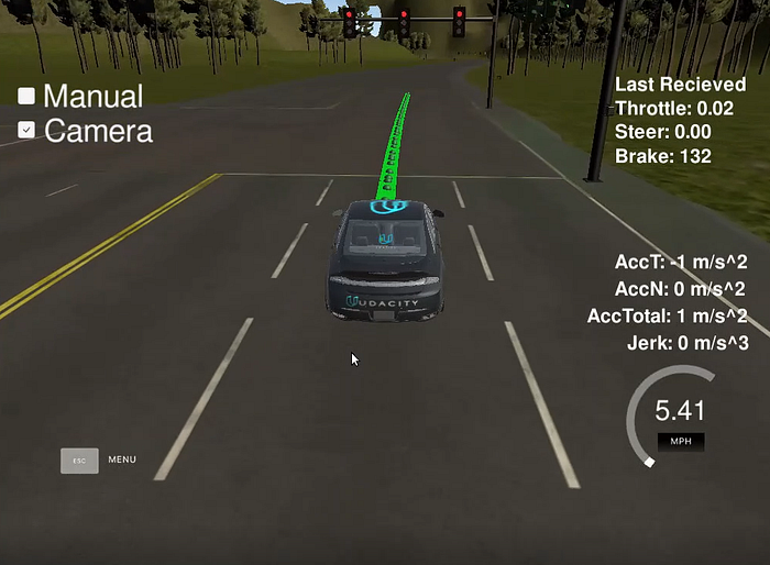
After training and testing the model, here’s what it looks like when run in real-time.
Github repository for additional information:
Let’s move onto the Traffic Light Detection part of the perception subsystem. In the case of the simulator I was using, I was already given the data of the location of the traffic lights and their colour. Alternatively, I could’ve also built yet another Deep Learning pipeline to help manage the Traffic Light Detection system.
Using that traffic detection system, we’d simply just publish the state of the traffic light (red, green, or blue) via ROS to the subscribed nodes.
The way we’d get the data of the location of the traffic light is through our trajectory. If a traffic light is part of the path of the desired trajectory, then we’d be able to receive the state of the light which is published through ROS.
Planning
Just as we mentioned before, we’d use a waypoint updater algorithm to help create the desired trajectory.
When we plan for the desired trajectory, we generally want to ensure that the car does not move backwards and usually forwards when driving (obviously there are situations where taking a step back is good, but we’re ignoring that in this case).
Instead, what we can do is simply make a check and see if our current waypoint (think of it as an interval in the trajectory) is in front of the car or not (I did a dot product multiplication to help figure this out).
From there, I’d get an output value. If this value is > 0, then it’s a waypoint in front of me allowing me to continue moving on that trajectory. If the output value is less than 0, then that waypoint can be discarded, therefore signifying that I’ve made progress on following the trajectory.
Also in the case that there’s an object in front of me or I’m at a traffic light, I’d need to deaccelerate my waypoints (trajectory) and ensure that I’m in time before I hit a car or break a law. We can do special thresholding that our car’s speed becomes the actual speed limit and as I continue to drive, I need to make sure I’m moving at a slower speed than I was at one timestep before.
For figuring out how we even create the trajectory in the first place, we can use a Polynomial Trajectory Generator to solve this problem. We can use our sensor fusion data to help us figure out a path we can legitimately drive on.
Because the intention of the article is to keep this stuff extremely high-level, take a look at this article for more info + technical logistics.
Control
For the control subsystem, we’d be using a DBW node to help control the car’s throttle, brake, and steering. We can mainly do this through the use of a PID controller.
Generally, when driving, we have something known as the crosstrack error. When driving, the crosstrack error (CTE) would be the center of our lane. We want to make sure that we’re driving in the center of the lane to ensure that we don’t veer off the center and potentially hit another car.
The whole PID controller is based on this error: P standing for Proportional, I for Integral, and D for Derivative.
We say proportional with respect to the current error (crosstrack error) to help get an output proportional to the CTE. Think of the proportional (P) controller as a form of “feedback” as it’s completely based on the CTE.
The I part (Integral) of the PID Controller basically takes the integration of the CTE error. What this means is that we’d take the sum of all the CTE errors and use that as a variable to tweak. By using the deviations which are affected with proportion to the sum of their magnitude, we can eliminate any offset (swinging behaviour) when driving, allowing the car to be more centred.
The D controller (Derivative) should be pretty state forward. In the case of our integral and proportional values being extremely high, by taking the derivative of those values with respect to time, we can now get a smaller output for a steering angle. This ensures that we don’t make sudden changes when driving and if there is a desired steering that is to take place, it can be done safely without unusual steering behaviour.
We can also threshold our driving: in the case that our desired PID values is to continue driving straight and if our velocity is below some certain threshold, then we can put the car on brakes to assume that we’re either at a traffic light or that there’s an object in front of us.
Results
Feel free to take a look at the Github code to run the code yourself!
Planning for the future
Due to COVID circumstances, I, unfortunately, haven’t been able to run the code on Udacity’s real, self-driving car (if you’re a Udacity employee reading this right now, send me an email please!!!)
Obviously, this isn’t close to a car I can actually drive in myself and take me wherever I’d really want. I think there is massive potential for improvement and potential opportunities to continue exploring + making an impact in the self-driving car space!
I’m currently fascinated by using camera inputs to perform lane detection in extremely adverse conditions (snow, fog, etc.). If you do know anyone who’s doing some research in this space, I’d love to connect with them! Please send me an email to them, it’d mean the world! Here’s my email: sri.anumakonda06@gmail.com.
Additionally, I’m also open for internships anywhere in the self-driving space. If you know anyone (or you) who would like to take me in as an intern or talk about potential working opportunities, feel free to send me an email using the link above.